The Ultimate Guide to Architecture Blueprints
If you have experience with the construction process, you likely have a good idea of what a blueprint is. This drawing is a form of communication between anyone who’s working on the project and is used to copy construction and architectural drawings. Architectural blueprints once had white lines that were placed on blue backgrounds. However, modern blueprints have blue lines with white backgrounds.
Architects often use blueprints to plan new buildings. Even though these professionals currently create these building drawings on computers, they used to be hand-drawn on paper. In this guide, you’ll learn all there is to know about architecture blueprints and what they are used for when developing a building.
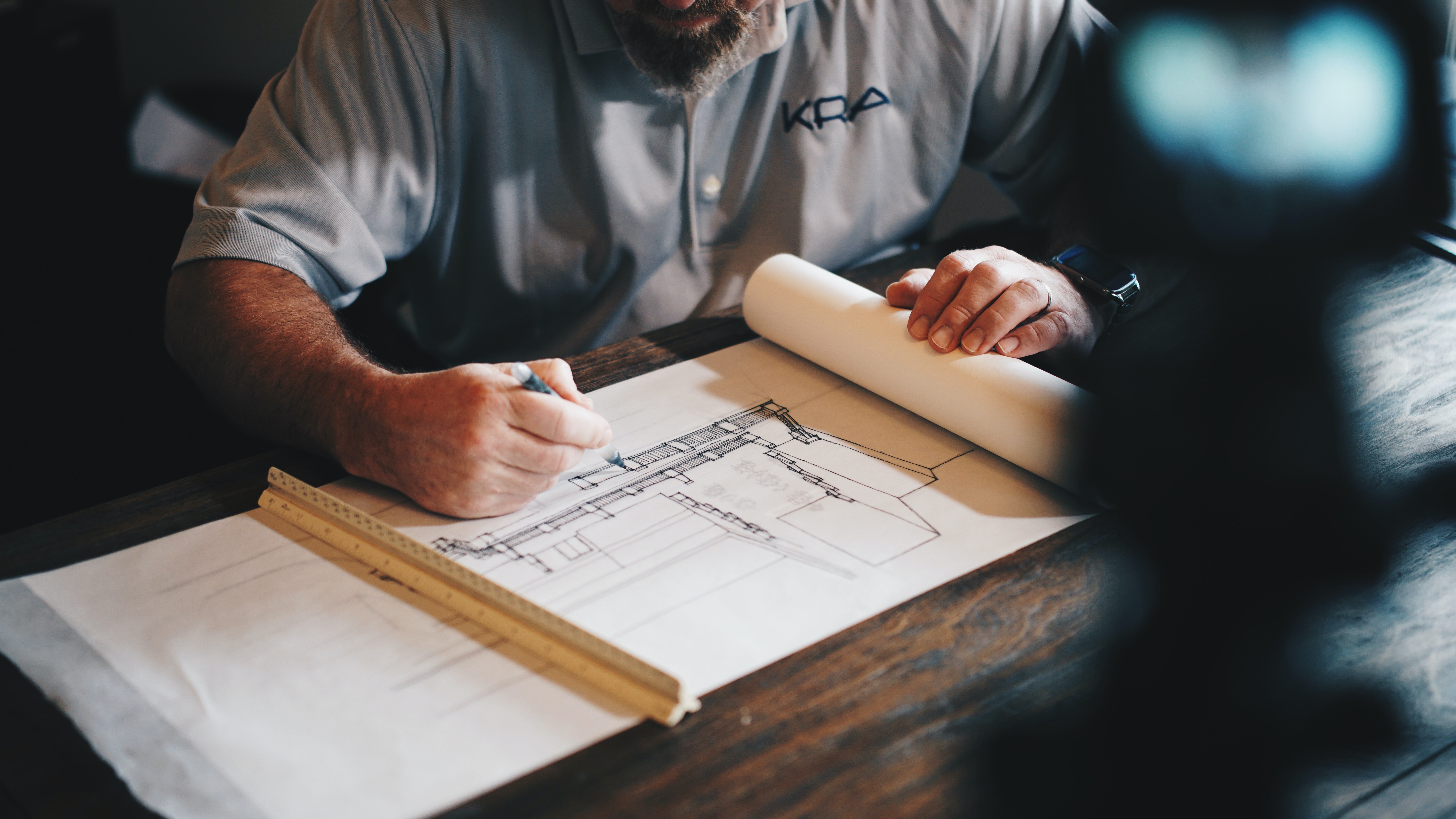
What Are Architecture Blueprints?
Blueprints are commonly used to reproduce engineering or architectural drawings by drawing on light-sensitive sheets. These drawings were first introduced by John Herschel in 1842, after which they quickly became the primary method for precisely producing an unlimited number of drawings. Blueprints are still widely used among architects and engineers.
The process that occurs when creating blueprints is what provides these documents with their distinctive color. First, a drawing is made on translucent tracing paper. The paper will then be placed on a sheet of paper that’s coated with potassium ferrocyanide and ammonium iron citrate. This is the main blueprinting paper. When these substances are first mixed, they form into an aqueous solution. This solution dries before the blueprinting paper is made.
When the two papers are placed together and positioned in front of bright light, the chemicals will react to create a blue compound known as blue ferric ferrocyanide. Any parts that aren’t blue are the lines from the original drawing. This process results in a negative white image being placed against a blue background.
The reason why blueprinting became popular among architects and engineers is because it was less expensive and more efficient than hand-tracing. While copier machines and carbon copying provided additional efficiency gains when compared to blueprints, professionals who work in construction still rely on blueprints for large-scale drawings.
In fact, architectural blueprints are still highly inexpensive when compared to using large-format copying machines, which is why it’s unlikely that they will go out of fashion in the near future.
Blueprints vs. Plans
Plans are scaled drawings of a portion of a building or the entire building. These drawings display the placement of appliances, fixtures, and openings. You can use a plan to assist you during the material selection, planning, construction cost estimation, and square footage calculation processes. It’s possible to view rooms from a top-down view with the roof of the structure removed. When compared to standard floor plans, blueprints are much more technical and detailed. A set of blueprints is comprised of:
- Electrical drawings
- Mechanical and plumbing systems
- Cross sections
- Plot plans
- Roof plans
- Foundation and basement drawings
- Framing plan
- Elevations
- Floor plans
Blueprints are typically drawn on sheets of paper that are sized at 18″ x 24″ or 24″ x 36″.
Creating Blueprints
The types of tools that you’ll need to make a blueprint include:
- Tracing paper
- Masking tape
- Architect’s scale
- Pencils and pens
- Flat working surface
- T-square
- Ruler
- Eraser
- Compass
Make sure that you place the title block at the right corner of the sheet. The information that should be included in the title block extends to the scale of the drawing, name of the view, name of designer, and date. You can start by drawing the building’s exterior walls before moving on to interior walls.
The next components that should be drawn are the windows and doors. From here, you should label all of the rooms before locating the appliances and fixtures. Floor surfaces can be labeled as well. Make sure that you include electrical symbols where necessary.
Your drawings need to consist of the right dimensions for the closets, cabinet depths, rooms, and distances from appliances to walls. The final aspect of drawing a blueprint involves creating a door and window schedule.
Reading Blueprints
Reading a blueprint is essential if you work in the architectural or construction industry. The main aspects of a blueprint that you’ll need to understand include the:
- Title block
- Revision block
- Notes and legends
- View determination
- Scaling
- Grid system
- Doors and windows
- Appliances
As mentioned previously, the title block includes everything from the name of the blueprint to the location that the blueprint is displaying. This aspect of a blueprint makes it easier to properly document it. The signatures and approval date are included below the information mentioned above.
The revision block is necessary whenever changes occur with the building. In this scenario, the drawing is redrafted, after which all changes are mentioned in the revision block.
Most blueprints contain numbers and symbols that differ from the basic lines and grids, which is why legends are essential. Learn all of the symbols on a blueprint if you want to understand the drawings. The notes on a blueprint highlight the specifications of the drawing and all other information that the main designer feels will help people understand the plan. Of the dozens of different symbols and abbreviations that can be placed in blueprints, the most common ones include:
- Arch. – Architectural
- Bldg. – Building
- Cab. – Cabinet
- C.D. – Construction document
- CL. – Closet
- Dim. – Dimension
- DWG. – Drawing
- Ext. – Exterior
- FL – Floor level
- GL. – Glass
- HV – High voltage
- J-box – Junction box
- LM – List of materials
- P.L. – Property line
- FT. – Square feet
- IN. – Square inches
There are three perspectives that are commonly used with 2D blueprints, which include sections, elevations, and plans. You need to know which one has been used when reading these drawings. Plan views display the drawing from a bird’s eye view, which means that the length and width of spaces are accurately indicated.
An elevation is a view from one of the sides of the property. This view is necessary for calculating height dimensions. A section is a view of the space if it was cut through. This view is an imaginary one that’s regularly used by architects to display the inner aspects of the construction process and how materials are set up.
When considering scaling, blueprints don’t represent the precise measurement of buildings but instead display a scaled-down version. The scale included on the blueprint tells you what the measurements found on the blueprint are equal to in the real world.

You can locate grid systems along the horizontal and vertical axis of the blueprint. These systems consist of letters on one end and numbers on the other. You can use this information to reference where objects are located. It should also be easier for you to reference the most important aspects of the drawing. If you’re discussing the drawing with an individual who isn’t at the construction location, the grid system should help you describe what you’re talking about.
When trying to find the windows and doors on the blueprint, the doors are usually represented by large gaps in walls that consist of curved lines around the door frame. The curved lines tell you if the door swings out or in when opened. A similar approach is taken with windows. The blueprint you’re looking at should consist of window and door schedules that include details on the material style, door/window shape, and size.
The final step in this process involves identifying appliances, which are represented by simple materials. The sinks, stoves, toilets, and fridges should be easy to locate. You may also see a finish schedule that describes the model and style of the different appliances that are currently or will be installed in the building.
Permits and Blueprints
When you apply for a building permit that will allow you to construct a new residential or commercial building, you’ll need to provide the LADBS with blueprints and any other building plans that have been made during the design phase of this process.
If the blueprints you give to the LADBS aren’t accurate or were poorly made, this could be a roadblock that you would need to navigate to have the permit approved. The permit approval process can take anywhere from a couple of weeks to more than 12 months depending on the size of the building and complexity of the project. A building permit expediter can speed up this process.
Conclusion
Today, blueprints are routinely viewed on displays instead of being printed on paper sheets. Even some older blueprints have been digitized to reduce the amount of paper that needs to be stored. Regardless of what form blueprints come in, they are essential when designing any building. They give you a comprehensive visual representation of what the architect wants the building to look like.
When you work with blueprints, the aforementioned tips and recommendations should help you navigate this drawing and identify any components contained within. Read up on the most common abbreviations before getting started.

Jason Somers, President & Founder of Crest Real Estate
With over 15 years of professional experience in the Los Angeles luxury real estate market, Jason Somers has the background, judgement and track record to provide an unparalleled level of real estate services. His widespread knowledge helps clients identify and acquire income producing properties and value-ad development opportunities.
Learn more about Jason Somers or contact us.

