How to Read Blueprints for Construction Planning
When you want to begin any type of construction project, among the most important elements of the entire process involves creating and reading blueprints. A blueprint is a type of two-dimensional drawing that’s usually made by an architect. The purpose of this drawing is to represent what the architect believes the finished building should look like. Most blueprints will specify the building’s dimensions, what construction materials are set to be used, and how the building components should be placed.
While blueprints were once made on blue paper with basic white lines, they are now commonly drawn on white paper with blue lines. The modern construction process requires a set of blueprints for many different areas of the home. Construction drawings, house plans, building plans, and floor plans are all considered to be types of blueprints. While several different professionals can create the blueprints for your construction project, they are usually drawn up by a professional architect.
The total amount of time it takes for an architect to complete a set of blueprints depends on the scope of the project and the type of building that’s being made. Keep in mind that these blueprints will go through several drafts before being finalized. For the standard construction project, you can expect this process to take around 1-4 months to be completed. On the other hand, it can take upwards of 3-10 months for an architect to draw up blueprints for a large commercial building.
If you hire an architect to make blueprints for your building, it’s important that you factor this period of time into your construction timeline. If you would like to speed up the process in other areas, consider requesting the assistance of a permit expediter to make sure that you receive your building permits without delay. Blueprints are practically essential for any construction project as they allow everyone who is involved in the project to get on the same page. Blueprints are necessary for estimating the bill of materials and cost of labor, obtaining the right building permits, and creating a construction timeline. The following article provides you with a detailed guide on blueprints and how to read them.
Types of Blueprints
There are three basic types of blueprints, which are distinguished from one another by the viewing angle perspective. The three types of blueprints that can be drawn include:
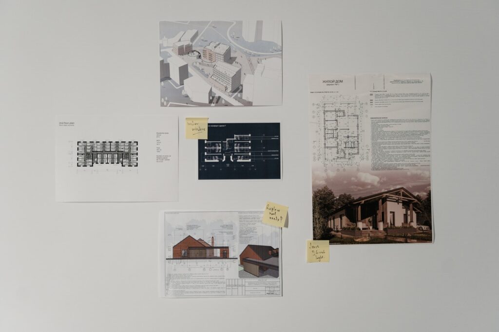
- Plan view drawing – This type of drawing occurs on a horizontal plane and is meant to display a bird’s eye view of the structure. Since the structure is being viewed from above, each floor must have its own drawing.
- Elevation view drawing – This type of drawing is done on a vertical plane, which allows the structure to be displayed from the back, front, right, or left side. It’s possible for elevation blueprints to be drawn from the interior or exterior.
- Section view drawing – This type of drawing occurs on a vertical plane, which makes it similar to the elevation view drawing. However, the drawing is meant to duplicate the interiors of a specific section of the home to provide the architect with a cross-section view. This view can show sheathing, insulation, wall studs, and wiring.
The unique perspective of each of these drawings is why they are used to display many different aspects of a home. Plan view drawings are considered to be the most popular of the three blueprint types.
Drawings in a Set of Blueprints
When you or the architect you hire is creating a set of blueprints, there are numerous pages that can be drawn during this process, all of which are likely necessary for your project. The primary types of drawings that can come in a set of blueprints include:
- General sheets – These sheets include the main cover sheet, title block, plan index, and any plot plans.
- Architectural plans – These drawings are designed to display the roofs, walls, floors, ceilings, and sections of the building.
- Structural engineering blueprints – These drawings outline the roof structure, building foundation, and framing plans.
- Electrical plans – These plans display the function and location of outlets, panel boxes, pictures, and electrical fixtures.
- Mechanical plans – These plans show where the control wiring, ductwork, piping, and HVAC system will be installed.
- Plumbing sheets – These sheets allow the architect the identify where the plumbing system is set to be located, which is necessary to avoid making costly mistakes while the construction process is ongoing.
Some of the other objects that can be included in blueprint drawings include windows, doors, and finish schedules.
How to Read Blueprints

When you want to learn how to read blueprints, doing so is fairly straightforward if you have a decent understanding of what you’re looking at. To get started, it’s important to understand that most blueprints will include a basic cover page, a title block, keynotes, some general notes, a drawing scale, a legend, and a revision block. If you understand what these elements are, it shouldn’t be too difficult to read a set of blueprints.
Among the most important aspects of a set of blueprints is the title block, which is positioned towards the start of a set of blueprints. Keep in mind that the title block can vary in shape, placement, and size. This portion of the blueprints will include the name of the architect or company that created the blueprints, copyright information, the creation date, the revision date, the sheet number, and the overall scale of the drawings. Make sure that every space within the title block is filled in.
As for the revision block, this aspect of the set of blueprints is meant to record the date of any changes that have been made to the structure’s design. If a component or system of the building is changed, the blueprints will need to be redrawn. When this occurs, any change must be listed on the revision block. It’s also important that you include a drawing scale with your blueprints, which will help the construction crew understand the scale at which the structure should be built. The blueprints you create will always display the structure at a ratio of its actual size. A common scale for blueprints is 1/8″=1′, which means that one-eighth of an inch on the blueprint equals one foot on the construction site.
Likely the most important aspect that’s included in every blueprint is a legend. The various symbols that are used in the blueprint are defined in the legend, which makes it much easier for other members of the construction team to read the blueprints. When you’re creating a legend for a set of blueprints, you should include every symbol alongside words that describe what the symbol represents.
Tips on Reading Blueprints
If you’re trying to read a set of blueprints that were created by another architect, there are several tips that should make it easier for you to read these blueprints. First, make sure that you start with the title block to gain more information about the blueprints and who created them. You should then focus on studying the legend before reading the blueprints. Otherwise, you may need to reference the legend every time you come across a symbol that you don’t understand.
Once you’ve familiarized yourself with the blueprint’s legend, you should locate its scale and orientation. As mentioned previously, every blueprint is drawn to a specific scale. If you don’t know what this scale is, you’ll have a difficult time understanding what the dimensions of the building should be. Locating this aspect of the blueprint is of the utmost importance. Without understanding the building’s scale, you could order materials that are incorrectly sized, which is a mistake that would be expensive to fix.
It’s also important to search for a compass scale or north arrow to identify the blueprint’s orientation. The orientation is usually located near the blueprint’s legend. The final suggestion you should keep in mind is to look for any notes that the architect may have made. These notes may be able to give you more context on certain aspects of the blueprint that were difficult for you to understand. While these notes could be written on the drawings, they could also be found on a separate document.
Reading Blueprint Lines
There are 10 different lines that could be included in a blueprint drawing. While it can take time to learn how to read the many different blueprint lines, understanding how to do so means that reading any future blueprints will be relatively easy for you. The 10 blueprint lines that you should be aware of include:
- Object line – This line has a solid and thick appearance. It displays the sides of a specific element that can be seen when viewed in person.
- Hidden line – These lines are comprised of short dashes that have half the width of the object lines. They show object surfaces that can’t be seen in person.
- Center line – These lines alternate between short and long dashes and are as wide as object lines. They show the central axis of an element.
- Dimension line – A dimension line consists of two lines that have arrowheads that point in opposite directions. These lines represent the distance from one point to another.
- Leader line – This is a very thin line with an arrowhead that points towards a certain building element. It can connect a number or note on the blueprint to the building element that it describes.
- Extension line – These are relatively short and solid lines that can be placed at the ends of dimension lines. They signify the limit of an element’s dimensions.
- Phantom line – This is a single long dash that’s followed by two short dashes. It displays how one building component can move to a separate location.
- Section line – This line consists of at least two parallel and diagonal lines. It’s meant to show when an object’s surface along the sectional view has been cut on the cutting-plane line.
- Cutting-plane line – These are U-shaped lines that have arrows at both ends. These lines bisect a specific building element. They are designed to show a building element’s interior features.
- Break line – These lines can be drawn as short break lines or long break lines. A short break line is drawn with a thick and wavy appearance. A long break line is drawn with a ruler and includes zigzag patterns. These lines are meant to shorten the length of a particularly long building element.
Now that you have comprehensive knowledge of how to read blueprints, it should be easier for you to plan the construction process without running into things you don’t understand. Whether you are in charge of the entire construction process or are working with one of the construction crews, knowing how to read a blueprint now will help you avoid making mistakes later on.

Jason Somers, President & Founder of Crest Real Estate
With over 15 years of professional experience in the Los Angeles luxury real estate market, Jason Somers has the background, judgement and track record to provide an unparalleled level of real estate services. His widespread knowledge helps clients identify and acquire income producing properties and value-ad development opportunities.
Learn more about Jason Somers or contact us.