Understanding Plan, Section, and Elevation Architectural Drawings
There are many different drawings that architects use when creating the design for a building or structure. Three of the most common drawings include plan, section, and elevation drawings, which represent various perspectives of a building’s design.
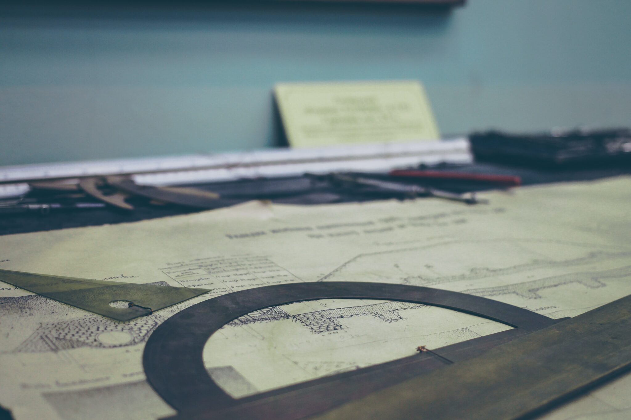
Plan drawings are displayed on a horizontal plan that shows you the view of the structure from above. Elevation drawings take a vertical approach when indicating what the property will look like. Section drawings are also vertical drawings but are made by cutting through the space to display many of the components that are found within the building. The following guide offers a detailed look at plan, section, and elevation architectural drawings.

What are Plan, Section, and Elevation Architectural Drawings?
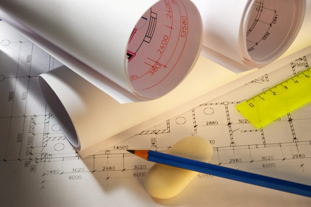
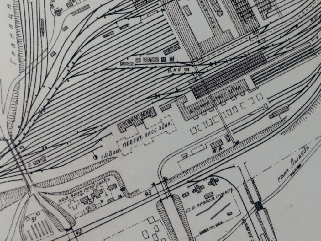
Plan drawings are used by architects to show a section of a building or the entire building. It’s drawn on a horizontal plan with a viewpoint from above. These drawings are commonly used by architects and engineers when displaying a graphic representation of a building. There are numerous types of plan drawings, which include:
- Plan
- Plan call out
- Plan detail
- Roof plan
- Reflected ceiling plans
- Plan perspective
- Site plan
Elevation drawings can also show either a portion of a structure or the entire structure. The elevation is shown via a vertical plane that looks directly at an interior surface or building facade. There are numerous types of these drawings, which include:
- Elevation
- Elevation call out
- Interior elevation
- Elevation detail
As for section drawings, they are meant to show the structure a vertical plan that’s sliced through a building. If you were to cut into a space vertically and stand in front of it, you would have the perspective that’s displayed on a section drawing. The various types of these drawings that architects work with include:
- Section
- Section call out
- Site plan
- Plan detail
- Reflected ceiling plan
Site plans can be made as section drawings or plan drawings.
Individual Uses of Plan, Section, and Elevation Drawings
Different drawings have different uses during the design process. Plan drawings show the layout of a structure from a top-down view, which provides architects with a better understanding of where everything will go and what the structure’s square footage is.
Section drawings provide you with a better idea of what the internal aspects of a building look like. Many important items that wouldn’t be displayed with elevation or plan drawings will be shown here.
When an experienced architect creates a section drawing, they are able to show rich and intricate details that provide the drawings with more information and visual references. It’s common for clients to view section drawings in order to understand how the interior spaces fit together. Builders will use these drawings to make sure that every facet of the building is constructed as planned.
As for elevation drawings, they are highly useful when performing comprehensive renovations. For instance, an elevation drawing is regularly used made a new kitchen design. These plans allow you to see information that standard floor plans are unable to accurately convey. For instance, cabinetry details and the sizes of drawers are viewable with elevation drawings.
While these drawings aren’t needed for all renovation or redecorating projects, they can be beneficial when you’re designing entertainment spaces, commercial spaces, bathroom vanities, bars, or fireplaces.
Why Plan, Section, and Elevation Drawings are Crucial to Architecture
Plan, section, and elevation drawings are regularly required for development applications. Architects can submit these drawings to the planning department to make sure that the structure adheres to development standards. These three drawings are able to provide everyone who works on the project with an understanding of what the design is supposed to be. Maintaining clear and accurate communication throughout the design process is essential if you want to minimize mistakes.
When it comes to section drawings, they are essential to help stakeholders learn about a building’s inner workings. This type of drawing connects information from exterior views and elevations to the interior views and floor plans.
Elevation drawings will save you from extra costs and unpleasant surprises during the construction process. If architects and builders use different drawings, errors would be more likely. If you’re performing a renovation, an elevation plan can expedite the approval process and assist you in estimating the project timeline and construction costs.
Keep in mind that elevation drawings can be exterior views of a building facade or interior views that allow you to see each room. These drawings are displayed with a flat plane. However, line weights and different amounts of shading can add depth to the drawing if needed.
It’s common for exterior elevations to have the same scale as floor plans or plan drawings. However, interior elevation drawings are more detailed, which means that they’ll likely have a larger scale when compared to plan drawings.

Use Cases for Plan, Section, and Elevation Drawings
Plan, section, and elevation drawings can be used in residential, commercial, and industrial projects. As mentioned previously, elevation drawings are routinely used during home renovations because of the extra detail they provide.
Whether you’re developing a commercial, industrial, or residential building, these drawings will help you create efficient and functional designs that highlight every component and element of the building in question.
For instance, section drawings show architects the thickness of roof slabs, outer walls, doors, and windows. This information can then be applied by the construction crew to select the right materials when constructing the building. Keep in mind that local planning departments require section drawings to determine if a building permit should be issued.
Tips for Reading and Understanding Plan, Section, and Elevation Drawings
Every drawing has different symbols, conventions, and dimensions that you’ll need to know if you want to read them with ease. As an example, let’s take a look at elevation drawings. There are hundreds of different symbols that can be placed on an elevation drawing. These symbols differ depending on the type of building that’s being constructed. The most common symbols include:
- Divider – A divider symbol is used to show that something is dividing an entire area or room into more than two separate parts.
- Frame – Frames are rigid structures that are placed around doors, pictures, or windowpanes.
- Drawer – The drawer symbol represents a storage compartment that can slide in and out of desks.
- Desk lamp – These symbols are used for items that are placed on desks and tables.
- Drainage pipe – When a pipe symbol is used in an elevation drawing, it represents piping that moves water away from the bathroom or kitchen area.
Since elevation drawings are meant to display the details of a room, the symbols that are used on these drawings are easy to understand. When you’re trying to read an elevation plan, you should first identify the title and scale aspects of the drawing. The title tells you which side of the structure the drawing is displaying. Architects often use compass directions in this area. As for the scale, it tells you how the building on the piece of paper compares to the structure as it exists in real life.
Elevation drawings will show openings for windows and doors, which will come with grills, trim, and other accessories. The roof pitch that an architect places on this drawing tells the builder exactly how steep the slope of the roof is. The symbol that’s used for the roof pitch shows two numbers, which include a run and a rise.
These drawings will also include elevation markers, which are dashed lines that tell you where the plate and floor lines for each level of the structure correspond with the elevation.
Plan drawings use similar symbols but can be highly varied depending on the materials that are used during the construction process. For instance, a concrete wall may be speckled with dots to indicate the material that’s being installed. Door symbols can also differ depending on the type of door that’s being used in the home. An example of some of the abbreviations that you’ll encounter on a plan drawing include:
- CAB – Cabinet
- CW – Cavity wall
- CT – Ceramic tile
- CTYD – Courtyard
- CL – Closet
- CNTP – Countertop
- DW – Dishwasher
- DBL – Double ovens
Conclusion
Plan, section, and elevation architectural drawings are all used by architects and builders alike to communicate important information during the design and construction processes. Many projects use all three drawings to make sure that every design element is understood. While plan drawings help the construction crew understand the floor plan, an elevation drawing shows where everything goes. Once you learn how to read these drawings and when they should be used during development, you can start creating them yourself.

Jason Somers, President & Founder of Crest Real Estate
With over 15 years of professional experience in the Los Angeles luxury real estate market, Jason Somers has the background, judgement and track record to provide an unparalleled level of real estate services. His widespread knowledge helps clients identify and acquire income producing properties and value-ad development opportunities.
Learn more about Jason Somers or contact us.